


Overview
Online monitoring and fault diagnosis are essential for ensuring transformer safety and power system stability. Dissolved gas analysis (DGA) in oil is the most widely used method for monitoring oil-filled electrical equipment. Photoacoustic spectroscopy–based DGA provides maintenance-free operation, real-time monitoring, and high accuracy for reliable condition assessment.
Principle
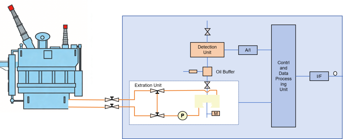
The system is based on infrared photoacoustic spectroscopy using a pulsed infrared light source and 7 mid-infrared narrowband channels for multi-gas analysis. Ultra-high sensitivity is achieved through a patented enhanced cantilever optical microphone, providing a wide linear dynamic range. Narrowband optical filtering and multiple spectral regions effectively suppress background interference and reduce cross-sensitivity.
Features - Online Model
l Sub-ppm level detection limit
l Fast oil-gas separation, with technology to eliminate temperature and humidity effects on gas distribution coefficients
l High electromagnetic compatibility meeting GB/T17626 and IEC61000 standards
l Two-level alarm function, with remote alarm signals
l Open database, compatible with local area power system networks
l Faster analysis cycle, with the shortest monitoring cycle of 1 hour, user-configurable (recommended at 12-hour intervals)
l Two-level gas threshold and growth rate alarms, with adjustable concentration and growth rates
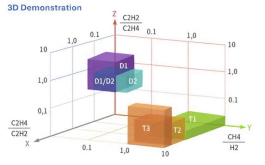
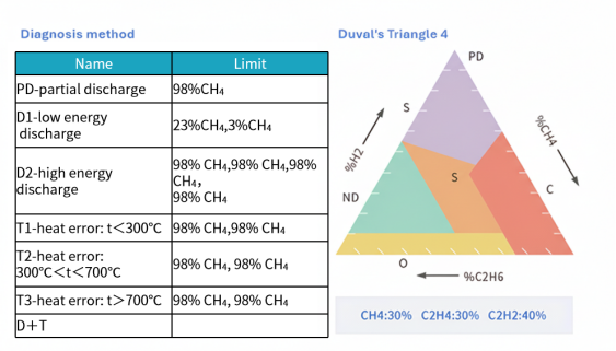
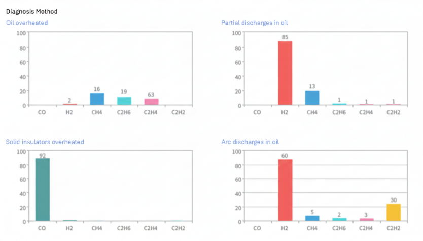
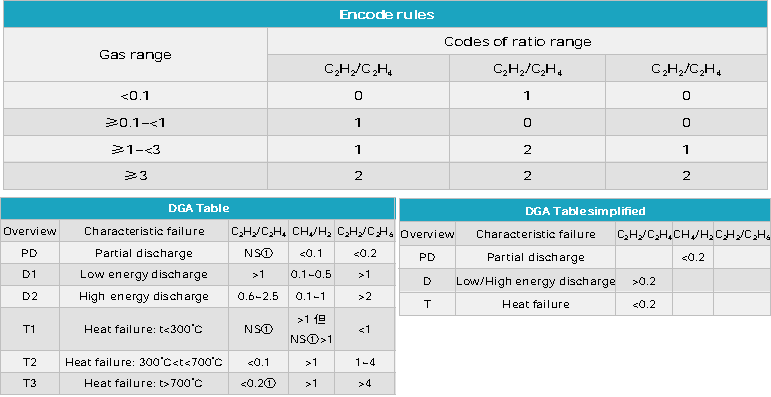
l Expert system for latent fault diagnosis, utilizing IEC60599 and improved fuzzy methods, Duval triangle, and cubic diagram methods
l Historical data trend charts, report formats for display and printing, enabling analysis of transformer operation and fault trends
l Supports IEC 61850 communication standards, optional fiber optic or twisted pair
l High system integration, with optional iron-core ground current and temperature/humidity monitoring
l Dual-loop, multi-mode temperature control with precision of ±0.1℃, automatic air conditioning
l Optocoupler isolated circuit design for improved anti-interference performance
l Ehernet-based full-digital remote data transmission, control, and parameter settings
l High expandability, easily integrated with other monitoring devices
l User-friendly software interface, fully in English, simple operation, and feature-rich
Features - Portable Model
l Portable case for onsite testing
l High-resolution graphical display interface
l Programmable measurement tasks
l Graphical and tabular display of all gas measurements
l Built-in trend monitoring tasks, no external computer or consumables required
Technical Parameters
Range | |||
Gases | Lower Limit /ppm | Upper Limit /ppm | |
H2 | 5 | 5,000 | |
CH4 | 0.1 | 50,000 | |
C2H6 | 0.1 | 50,000 | |
C2H4 | 0.1 | 50,000 | |
C2H2 | 0.1 (Portable 0.5 ppm) | 50,000 | |
CO | 0.5 | 50,000 | |
CO2 | 0.5 | 50,000 | |
O2 | 0.5% | 80% | |
N2 | 0.1% | 50% | |
H2O | 100 | 100% | |
Physical and Mechanical | |||
Operating Temperature | +5~+50℃ | Sample Temperature | 0~+45℃ |
Storage Temperature | -30℃~+80℃ | Humidity | 90% non-condensing @30°C |
Vibration Resistance | IEC60068-2-6, Fc test | Shock Resistance | IEC6068-2-31, ISTA1A |
Power Input Frequency | 47~63Hz | ||
Power Input Voltage | Universal 90~250VAC | ||
Dimensions | 677mm x607mm x 560mm 51.85cm×23cm×40.5cm(Portable) | ||
Weight | <35.5kg <25kg(Portable) | Gas Chamber Volume | <30ml |
Dynamic Range | 100,000 | Zero Drift | ± detection limit/1month |
Reproducibility | 5% under reference | ||
Range Drift | 5% per 12 months | ||
Accuracy | ±5% or ±2 ppm (whichever is greater) | ||
RH Accuracy | ±1%RH(H2O 0~90%RH) | ||
Standards | |||
l EN61326-1:2006 Radiation Emissions (Class A); l EN61326-1:2006 Conducted Emissions (Class A); l EN61000-3-2:2000 Harmonics; l EN61000-3-3:2001 Flicker Testing; l IEC61000-4-2:2001 Electrostatic Discharge Immunity; l IEC61000-4-3:2002 Radiated Immunity; l IEC61000-4-4:2001 Electrical Fast Transients/Burst Immunity; l IEC61000-4-5:2001 Surge Immunity; l IEC61000-4-6:2001 Conducted RF Immunity; l IEC61000-4-8:2001 Magnetic Field Immunity; l IEC61000-4-11:2001 Voltage Dips, Short Interruptions and Voltage Variations Immunity; l EN61010-1 : 2001IEC61010-1UL61010-1 CAN/CSA-C22.2NO.61010-1 EN 50270:2006; l IEC61000-4-11:2001 Voltage Dips, Short Interruptions and Voltage Variations Immunity; l IEC 60599:2015 Mineral oil-filled electrical equipment in service ; l IEC 60567:2023 Oil-filled electrical equipment ; l IEEE Std C57.104-2008 IEEE Guide for the Interpretation of Gases Generated in Mineral Oil-Immersed Transformers; l ASTM D3612-12 (2022) Standard Test Method for Analysis of Gases Dissolved in Electrical Insulating Oil by Gas Chromatography; l GB/T 7252-2001 Guide to the analysis and the diagnosisof gases dissolved in transformer oil; l DL/T 1432.2-2016 Testing specification for on-line monitoring device of transformation equipmentPart 2; l DL/T 722-2014 Guide to the analysis and the diagnosis of gases dissolved in transformer oil; l DL/T 1498.2-2016 Technical specification for on-line monitoring device of transformation equipment-Part 2; l Q/GDW 11304.42-2021 Technical specification for energized device of electrical equipmentPart 4-2; l Q/GDW 10536-2021 Technical specification for on-line monitoring device of gases dissolved in transformer oil. | |||

 Company:
Lightwaves
Company:
Lightwaves
 Tel:
+31611264230
Tel:
+31611264230
 Address:
Bolderweg 1, 1332 AX Almere, The Netherlands
Address:
Bolderweg 1, 1332 AX Almere, The Netherlands
 Email:
info@lightwaves.nl
Email:
info@lightwaves.nl
Copyright © Lightwaves Website Map
